
M. E. Veis, S. N. Fadeev, N. K. Kuksanov, P. I. Nemytov, V. V. Prudnikov, R. A. Salimov and S. Yu. Taskaev
STABILIZATION OF ACCELERATING VOLTAGE IN HV ACCELERATOR-TANDEM FOR NEUTRON CAPTURE THERAPY
An electrostatic tandem-accelerator with vacuum insulation is being developed at BINP. Source of accelerating voltage is one of the component of the accelerator. In the work presented here a stabilization system of the output voltage of the HV source with an output voltage of up to 1.5 MV and a power of up to 100 kW is considered. The source is based on the cascade generator with an inductive coupling and parallel feeding of stages. The source is designed for producing accelerating voltage in the tandem-accelerator. Estimates of the output voltage ripple are given and methods for its suppression are proposed.
Introduction
Presently at Budker INP, a facility for the boron neutron capture therapy (BNCT) is being developed for curing malignant tumors under conditions of specialized hospitals [1]. To this end, it is suggested an accelerator based source of neutrons. The beam of H- ions is injected into an electrostatic tandem-accelerator with vacuum insulation. The beam accelerated to the full voltage reaches the charge exchange gas target where negative hydrogen ions are converted into protons. Then, the proton beam is accelerated again and at the output of the tandem accelerator it has and an energy of double accelerating voltage. When the proton beam is dropped at the lithium target, the neutron flux is generated due to reaction 7Li(p,n)7Be.
Two versions of the neutron source depending on the operation run are envisaged: therapy with fast neutrons and neutron capture therapy. The most attractive version is the boron neutron capture therapy. A tumor-seeking compound containing stable isotope 10B is introduced into blood and given time to be accumulated in the tumor. The tumor is then irradiated with epithermal neutrons, which are captured by 10B isotope. Capturing neutrons causes the boron nuclei to break apart, resulting in the emission of a -radiation and recoiling 7Li nuclei. Both a -particles and lithium are high in energy but short in range, which means that they destroy the malignant cells in which boron is embedded without hurting the adjacent healthy cells. Reaction 7Li(p,n)7Be is of the threshold character and near the threshold the neutron flux has good orientation forward and the optimal spectrum with an average energy of 30 keV. In the regime for fast neutron therapy, the proton energy should be 2.5 MeV and the spectrum maximum is shifted to an energy of 790 keV required for the fast neutron therapy and the beam orientation is provided by collimators. At the same time, the neutron beam also suitable for the neutron capture therapy can also be formed from this beam with the use of collimators and moderators.
Therefore, the source of accelerating voltage should have an output voltage equal to half a value of proton energy and depending on the generator operation run the voltage value should be equal to either 0.94 MV or 1.25 MV.
The rectifier load current is equal to a double value of the proton beam current whose value is determined assuming the reasonable time of exposure (about 10 minutes) for obtaining the required therapeutical dose (about 20 Gy). In the neutron therapy facility, the value 20-40 mA is considered as maximum [1], i.e. the maximum current consumed from the source is 80 mA.
The HV sectioned rectifier based on the accelerating voltage source for ELV-4 accelerator with maximum voltage of 1.5 MW [2] just satisfies these requirements. In addition to the fact that the HV-source provides the required parameters as the power and voltage, its attractive feature is its high reliability proved by the long term operation of tens of such accelerators using similar HV source at the industrial plants and research centers.
Design of HV-rectifier
The source of high voltage used in ELV type accelerators and some other types of ion accelerators is a stage generator with an inductive link and parallel feeding of stages, which is planned to be used in the project of BNCT.
Inside the tank filled with an insulating gas (SF6) there are: the primary winding, a column of rectifying sections, magnetic conduits of the return flow (bottom and cylindrical). The primary winding has 32 turns of the water cooled copper pipe. It generates the longitudinal alternate magnetic field with the feeding mains frequency of 400 Hz. The primary winding turns are isolated from the high voltage gap by an electrostatic shield made of a thin sheet of stainless steel.
Fig. 1. High voltage rectifier: 1 - high voltage electrode; 2 - high pressure tank; 3 - primary winding; 4 - rectifying sections.
In comparison with "conventional" transformers this design is distinguished by the absence of the central magnetic conduit. The primary winding is "wrapped" by the magnetic conduit. Two additional magnetic conduits are located at the bottom of tank and over the high voltage electrode. These magnetic conduits remove excessive heat caused by eddy currents.
The HV rectifier column consists of 37 rectifying sections connected in series. Each section is a coil of the secondary winding and a double voltage circuit based rectifier. The coil has 3000 turns separated by polymer-mica insulation. Maximum voltage of the coil is 20 kV. Thus, the section output voltage can reach the value of 40 kV. The number of sections connected in series determines the maximum output voltage of HV rectifier. Operating voltage of the coil in the project does not exceed 17 kV, i.e. the section voltage is 34 kV. For rectifying the alternate voltage CDL-0.4-800 columns with a current up to 0.4 A and maximum inverse current of 80 kV are used. An inverse voltage of columns does not exceed 34 kV during the source operation. K-15-10-type capacitors are simultaneously used as filters and for protection of HV rectifier elements (coils, diodes) against excessive loads occurred at breakdowns of the vacuum or gas insulation.
The accelerator primary winding is power supplied with an alternate voltage of 400 Hz from the frequency converter. Electric motor converters are attractive because of their low price, simplicity and reliability. They have an acceptable efficiency (65-80 % depending on power). In principle, the static frequency converters can be used as power sources (with the use of IJBT transistors). However, there is no any evident advantages of static converters except may be for their higher efficiency (they have an efficiency factor of 85-92 %).
Rectifier current-load characteristic
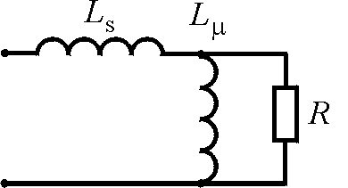
Fig.2. Stage generator equivalent circuit.
The stage generator circuit in its simplest form can be given as follows (Fig. 2):
Here, Ls is leakage inductance of HV transformer, Lm - magnetizing inductance of HV transformer, R is load resistance reduced to the magnetizing inductance of the primary winding.
Unlike the transformer with the central magnetic conduit, this version cannot avoid the leakage inductance even for a first approximation. The absence of the core and HV insulating gap between windings cause that Ls " Lm . In addition, the distributed intrawinding capacitance of the winding make the load to be resonant. The rectifier resonant frequency is about 1200 Hz. Since the source operating frequency is 400 Hz, the resonant characteristic does not affect substantially the rectifier operation. Presence of the rectifying diodes and filter capacitors make the circuit to be nonlinear. In the rectifier circuit under consideration, the large value of Ls leads to that with an increase in the load the pulse duration of current charging pulse through diodes increases to become equal to a half period and voltage at the secondary winding coils becomes to be rectangular (at sinusoidal voltage at the first winding output) [3].
In order to take into account these factors in operation [3] we introduced the notion and obtained the universal load characteristic for the transformer with a leakage inductance operated to the rectifier with an active-inductive load.
This characteristic shows the dependence of a decrease in a on the value w L1/RH, where L1 = Ls Lm / (Ls + Lm ), and RH is the load resistance reduced to the primary winding.
A decrease in a is equal to the ratio of the idle run output voltage to the voltage value under load. If the energy stabilization system keeps output voltage constant, a decrease in a is the ratio of the primary winding voltages U1 under the load and in the idle run.
![]() .
.
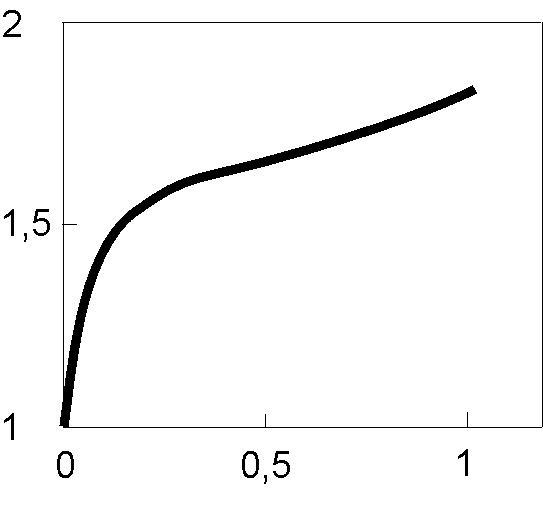
Fig.3. A decrease in a as a function of w L1/RH.
The load curve is given in Fig. 3.
Note that at small loads, voltage decreases faster because of larger content of harmonics in the diode current when the duration of the charge current is low. With the increase in the load, the current pulse duration increases and the relative content of harmonics decreases. Usually, in the source operation, the value of a larger than 2 is not used.
Admissible instability and admissible level of ripple
In the case of the conventional ELV-type accelerator, when an electron current is extracted into air through the titanium foil window, ripples and instabilities of the accelerating voltage lead to that the boundaries of the foil raster or irradiation zone on the material on the technological line are smeared. Because of this fact, the beam efficiency factor is slightly decreased. Much more important fact is that with an increase in energy the beam deflection angles increase and the beam can reach walls of the extraction system, which is inadmissible. Therefore, the maximum admissible value of the electron beam energy instability is taken to be ± 5 %.
In the case of extraction the focused beam into air through holes in a diaphragm, the beam is focused by two magnetic lenses and gas leaked through diaphragms is removed with continuously operated pumps of the differential pumping system. One of the main parameters determining the hole dimensions (and thereby gas leakage into the system) is chromatic aberrations of magnetic lenses. Here an admissible value of energy instability ranges within 1 - 2 %.
Requirements to stability of accelerating voltage in the neutron therapy facility are determined both by the beam passage through the line and the neutron generator operation run. In one version, a 90 degree turn of the proton beam is supposed. Assuming the proton beam displacement of 1 cm with a distance of 3 m to the neutron generating target admissible, we obtain requirements to the angular stability to be 3.2 10-3, i.e. D U/U " 5 10-3. In operation with the near-threshold run, where the proton energy ranges within 1.883 - 1.890 MeV, the stability requirements are harder and the required stability is 10-3. For another operation run with the proton energy of 2.5 MeV, there is at all requirements to the energy stability from the viewpoint of proton generation, and remaining requirements are to the beam passage. Thus, the accelerating voltage source stability for operation in the neutron-capture therapy complex should no worse than 10-3 [1].
Ripples of rectified voltage
In principle, all the HV source in the ELV-type accelerators are one-phase rectifiers operated at the capacitance load. As already mentioned, they are distinguished by the operation with larger cut-off angles (large duration of charge current pulses through diodes), which leads to a substantial decrease in ripples of output voltage. The total amplitude of the output voltage ripples is determined by the formula
![]() .
.
Here, Ň is the power voltage frequency period (in this case, equal to 2.5 ms); Ń is an output capacitance of the source, which consists of the rectifier capacitance, capacitance of the high voltage electrode, and capacitance of the tandem accelerator, to be equal to 400 pF. R is the load resistance, which is equal to accelerating voltage divided by the load current (in the case of BNCT, this a double proton beam current and minimum R = 15 Mohm; b determines the effective discharge time of capacitors:
![]() .
.
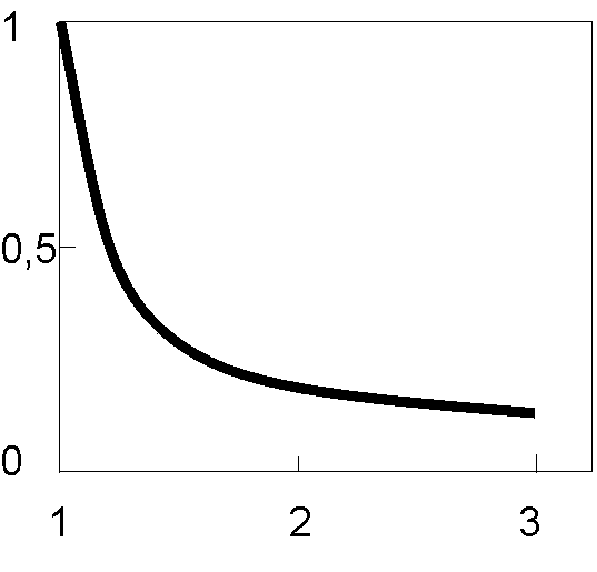
Fig.4. b as a function of current decrease a ..
Parameter b depends on a decrease a and this dependence is shown in Fig.4.
Note that the parameter tends rather rapidly to its ultimate
![]() .
.
In spite of the rather complex dependence of b on the load, dependence of ripples on the load current is of monotonic character and usage of ultimate values for estimates is justified.
By substituting numerical values in these formulae we get the value of output voltage ripples ± 2,5 % for current of 80 mA. These results were checked with the computer simulation using code NL. These analytical expressions just facilitate better understanding of processes.
Operation principle of energy stabilizing system of ELV
The stabilization system (by its operation principle) belongs to continuous a static systems with a closed cycle of control. Such systems enable one by rather simple methods to provide high accuracy, wide control range, high quality of intermediate processes

Fig. 5. Functional diagram of the system for stabilizing the output voltage of the stage generator.
Fig. 5 shows the functional diagram of the system. Control closed circuit comprises the following sections: control object consisting of the stage generator HVR and primary winding PW; ED meter device; ESU stabilization unit; control unit of frequency converter CCU; electromotor frequency converter with an excitation winding EW and power supply circuit of the winding ER; matching circuit for C impedances.
Consider briefly all the sections of the feedback loop.
Meter deviceIn the stabilization system, an acceptable accuracy is determined by accuracy of high voltage measurements.
Measurement devices used in ELV accelerators are either resistive divider or rotor voltmeter. The resistive divider is placed inside the high voltage sections. The rotor voltmeter is mounted at the upper cap of the tank over the high voltage electrode.
The simplest method for measuring high voltage is the use of voltage resistive divider. Unfortunately, in our country there is no wide choice of high accuracy high voltage resistors (microwire precise resistors of the type C5-23, C5-24 have too large overall dimensions and require special protection means against high voltage breakdowns, therefore, they hardly match the stage generator design). The most suitable (in its design) resistor of C3-14-type has an acceptable resistance bias of ± 10 %, resistance temperature factor ranges from - 2 10-3 to + 10-3 1/° Ń, that is clearly unsatisfactory for required accuracies. However, long term observation of the behavior of parameters at ELV accelerators equipped with energy dividers based on such transistors and calibration of these dividers with precise dividers have shown that accuracy parameters of these dividers can clearly be placed within 5 % scale. Such an accuracy is satisfactory for major technological applications of ELV accelerators. Note, that here we mean an absolute accuracy. The relative accuracy is a few times higher and with no account for temperature dependence it ranges from 0.5 to 1 %.
Penetration band of the resistive divider placed inside the high voltage column is limited to be a few fractions of a Hz by parasitic capacitive currents from shields of high voltage section shields.
In accelerators at energies higher than 2 MeV and power over 100 kW, the reliability of the divider operation decreases. This is related to the fact that with an increase in power the distribution of voltage over the high voltage column sections changes and rectified voltage ripples increase thereby leading to occurrence of the crown discharge causing the destruction of the divider. Therefore, for such machines we use a specially developed rotor voltmeter. The operation principle of the rotor voltmeter is based on the effect of charge induction (separation) at metal surfaces placed into electric field.

It is clear that in the insulating gas gap between the high voltage electrode HVE (see Fig. 5) and the grounded accelerator tank (VES) the electric field is generated. The intensity of the field E at every point of the gap space is proportional to the value of the applied voltage.
If we put the metal unmovable meter plate 1 and a shielded grounded plate 2 into an electric field of the high voltage electrode and start periodically to open and shield the meter plate from electric field, each time when we open the meter plate, there will be induced the charge Q whose value is proportional to the field intensity E. When closing (shielding) the meter plate, this charge will decrease down to zero. The change in charge will cause an alternate current in the measuring circuit whose value is proportional to the field intensity and therefore, to the high voltage produced by the field.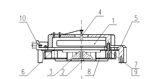
Fig. 7. General view of the rotor voltmeter.
Fig.7 shows general view of the rotor voltmeter. On the shaft of the direct-drive electromotor 1, fixed with screw 2 is a winglet (a movable shielding plate) 3, which is connected to the grounded body through the bronze-graphite contact 4. Electronic components of the rotor voltmeter circuit are placed on the printed circuit 6, which is jointly with the motor mounted on body 5 with rods 7. The measuring plate 8 made of foiled fiber glass is fixed with screws 9 under the rotating winglet at rods 7. There two oppositely located section holes in the winglet and four sections are etched at the meter plate. Each section is connected to the printed circuit with conductor and opposite sections are combined. Thus, the rotating winglet (in turn) closes/opens pairs of combined sections.
This rotor voltmeter is distinguished by its simple design, small overall dimensions (125 mm in diameter and 50 mm in height) and can easily be built in the accelerator design. The measurement accuracy is determined by the accuracy of input measuring circuits and temperature deviations of the gap between the high voltage electrode and voltmeter meter plate. Its value is of the order of 1 %.
The penetration band is determined by the angular rotation speed of the motor to be a few fractions of a Hz.
Under assumption of all mentioned above, one can make a conclusion that these kinds of measuring devices can provide an accuracy within 1 % in stabilization of the output voltage. This accuracy being acceptable for electron accelerators in technological applications is not enough for the BNCT project whose requirement to accuracy is 10-3.
Stabilization Unit
The stabilization unit compares an input reference signal of DAC and the output signal of high voltage meter, provides magnification of the error signal, forms the amplitude-frequency characteristics of the energy stabilizer parameters. The error signal amplifier is based on the PID-controller circuit. The proportional, integrating, and differentiating sections are based on separate precise operational amplifiers. By varying time constants of the integrating and differentiating sections and the amplification factor of the proportional section during the adjustment of the stabilizer, one can rather easily provide the controller stability keeping the high quality of adjustment. The unit is made using modern elemental base. The precise operational amplifiers are capable to provide the accuracy of no less than 10-4.
Converter Control Unit generates direct current for feeding the excitation winding of the frequency converter. The unit is based on the one-phase thyristor controller circuit. The thyristor activation phase is determined by the level of voltage from the stabilization unit output. Since the stabilizer adjustment time is large (of the order of 1 s), one can assume that the unit does not contribute substantial error into the system of stabilization.
Summarizing all mentioned above about the energy stabilization in ELV accelerators one can arrive at the conclusion that for the use of this stage generator in the BNCT project it is necessary: first, to improve accuracy of the measuring device, and second, to decrease ripples of the rectified voltage.
Stabilization of accelerating voltage of the tandem-accelerator
Fig. 8 shows the functional diagram of the system stabilizing an accelerating voltage and suppressing ripples of the tandem accelerator for the BNCT project. Compared to the conventional structure of the accelerating voltage stabilizing system used at ELV accelerator, this scheme is distinguished by a system of active suppression of the rectified voltage ripples.
In order to improve accuracy of measuring device in case of the rotor voltmeter usage, one should use the compensation-type voltmeter and provide mechanically high accuracy of its mounting with respect to the high voltage electrode. In principle, this solution is feasible but it is hard to be realized in practice. Therefore, we have chosen the version with resistive voltage divider. It can be made with resistors MG735 with nominal 100 Mohm, accuracy ± 0.1 % and temperature coefficient of 80 ppm/°C or TG950 with the same accuracy with temperature coefficient of 25 ppm/°C of CADDOCK ELECTRONICS (USA) production. This divider will provide measurement accuracy of high voltage at the level of 10-3. However, we have no experience in usage of these resistors in similar high voltage sources. Resistors can be aged and loose their linearity. In order to compensate for the resistor aging effect and for avoiding the dependence of the divider resistor resistance on the applied voltage, we plan to use an additional device for analyzing the beam energy of neutrals accompanying protons. Consideration of the device is beyond the scope of this publication. A signal from this device (CORR) proportional to the difference between the real and required energies is applied to one of the inputs of stabilizing unit and corrects the output voltage value of the resistive divider. Note, that during operation of this analyzer, requirements to the resistive divider accuracy decrease and the use of already tested resistors C-3-4 is possible.

Fig.8. Functional diagram of the stabilizing system and system for suppression of ripples in tandem accelerator.
Circuit of active suppression of ripples
As was shown earlier, the value of input voltage ripples for the stage generator at maximum beam current will be about ± 2.5%, that in absolute numbers is ± 25 kV. For suppression of these ripples, one should introduce the control element into the current rectifier circuit. Only electron tubes are operated in this range of energies. Thus, we can install the control tube at one of outputs of the high voltage source. When installing tube under high potential between the output of the accelerating voltage source and tandem accelerator, the tube is required to have an admissible anode voltage of little larger than the voltage ripple amplitude, i.e. in this case, one has to choose the tube with an admissible anode voltage of 60 kV. The ripple value can be measured with the voltage capacitive divider. A signal from the divider should be amplified and in the counter phase with ripples it should be applied to the tube grid circuit. In this way, high voltage ripples can be suppressed. However, when installing the tube under high potential, some difficulties occur, which are related to the tube cooling and its positioning in the compressed gas medium. From technical viewpoint, it is even harder to arrange the power supply of the tube filament and transfer the control signals from the "ground" to the tube grid.
Installing the tube from the side of the "ground" potential will require a higher voltage tube since, as calculations have shown, the transfer ratio along the chain - filtering capacitance of sections and section capacitances to the shield of the primary winding - does not exceed 1/3. However, the tube cooling problems could be solved much easier.
Having in mind all mentioned above, the high voltage control triode of GP-6 type with maximum admissible anode voltage of 180 kV is selected as a control element. The tube is operated with the "grounded" anode, therefore the filament power supply source (14.5 V, 100 A) should be galvanic insulated from the "ground". It is also necessary to insulate from the "ground" the poser supply source of the magnetodischarge pump built in to the tube.
A signal from the capacitive divider Ń1, Ń2 (see Fig. 8) is applied to the input of PA amplifier, which forms the amplitude-frequency characteristic of the feed back loop of the system for suppressing ripples. An amplified signal (through the optical coupling line) is appled to the input of the control source of grid voltage (0 - 4 kV). A signal from LD resistive divider (applied to the same amplifier) indicate the direct current operation run of the tube.
Conclusion
Thus, the output voltage stabilization in the high voltage source of a stage-type with and inductive link and parallel power supply of stages was considered, in particular, for purposes of the boron neutron capture therapy. The developed system enables one to keep the accelerating voltage within accuracy higher than 10-3. A system of active suppression of ripples allows to keep ripples of rectified voltage at the same level. The basic principles and methods used in the stabilization system can also be applied in other accelerators and electrophysical devices.
References
1. B. Bayanov, V. Belov, E. Bender, M. Bokhovko, G. Dimov, V. Kononov, O. Kononov, N. Kuksanov, V. Palchikov, V. Pivovarov, R. Salimov, G. Silvestrov, A. Skrinsky and S. Taskaev. Accelerator based neutron source for the neutron-capture and fast neutron therapy at hospital. Nuclear Instr. and Meth. in Phys. Res. A 413/2-3 (1998) 397-426.
2. R. Salimov, V. Cherepkov, J. Golubenko, G. Krainov, B. Korabelnikov, S. Kuznetsov, N. Kuksanov, A. Malinin, P. Nemytov, S. Petrov, V. Prudnikov, S. Fadeev and M. Veis. DC high power electron accelerators of ELV-series: status, development, applications. Radiation Physics and Chemistry 57 (2000) 661-665.