|
When a man begins to feel his age as substantial
he wants to write a book about his life, at least most of men. An approaching
of my fifty stimutates this attempt fo me. I try to do it in a modern way-
to create web page about may way.
I have been working with Institute of Nuclear Physics
since 1976. Most of my time was spent for automation hardware designs.
Each designed device should be supported by test software and a lot of
time was spend for application and test software designing. We used exotic
computers- ICL-1900. In 1984 my colleges designed CAMAC microcomputer which
replaced ICL-1900. It was very uncomfortable to work with this rare computer
and I wrote a few system component software (editor, text processor, print
utilities an so on) to increase a comfort of my job. In some years years
this side of my activity consumpted a lot of time. But my main activity
was hardware design. This page describes most of my hardware designs.
1976
I graduated Novosibirsk ElectroTechical Institute in
1976 and came in Institute of Nuclear Physics. The first year of my activity
was spent for designing conveyer ADC. As normal graduated student I was
learning hard, but most of ideas came from my teacher of those days- Mr.
Batrakov. That ADC had not bad parameters for those days- 8 bits and 20
Msamples per second. We assembled two devices with CAMAC interface and
memory in 1977, gave them to customers and that direction was closed (mostly
by my efforts).
1977
I had learned to something in that year, probably. A
few ideas appeared which contradicted to official policy in this field.
A personal design appeared. My institute bought first arithmetic-logical
unit IC and I wanted to use it in ADC. The idea was very simple- to make
tracking ADC with parallel comparator section. I assembled this ADC on
prototype board during one week-end. The device had 8 bits and could process
signals 80 KHz. It turned out that aparameters of this TTL device exceeded
pameters ECL tracking ADC which my colleges were designing at that time.
It was fine result and my device was recognized as a perspective one. This
ADC board was used in different models of our digital oscilloscopes (8100,
8100.2, 8500). I returned from my first vacation with three schematics
(tracking ADC board, successive-approximation ADC board (101) and
CAMAC interface board). These schematics were basement for digital oscilloscopes
family which we began to produce from 1978.
1978-1979
It is very difficult to recover a chronology these years.
There were designed and produced first digital oscilloscopes, first fast
analog multiplexer for them and auxiliary devices. It was time of appearance
of russian middle integration ICs and first memory ICs. That was a reason
for designing many versions of our digital oscilloscopes. A low level of
russian ICs allowed to implement a digital oscilloscopes on at least 3
PCBs. These version were produced from a pair ADC-boards (tracking ADC
and successive-approximation ADC boards), three memory boards (fast
memory on TTL and ECL ICs and low speed board on DRAM chips) and the single
CAMAC interface board.
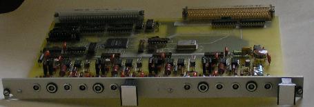
 Conveyer ADC. There were produced an prototype device and a
pair of oscilloscopes shown on photo. An ADC board consist of four
comparator sections which fixed 2 bits each section. A delay of analog
signal between sections was implemented by a coaxial cable (total
delay was 150 ns). This cable defined dimensions of device. There
were used digital ICs 100LP16 as fast analog comparators.
Conveyer ADC. There were produced an prototype device and a
pair of oscilloscopes shown on photo. An ADC board consist of four
comparator sections which fixed 2 bits each section. A delay of analog
signal between sections was implemented by a coaxial cable (total
delay was 150 ns). This cable defined dimensions of device. There
were used digital ICs 100LP16 as fast analog comparators.
The device provided 8 bits resolution, 256 words
of memory, 50, 200, 1000, 4000 ns time of measurements, four input
ranges. |
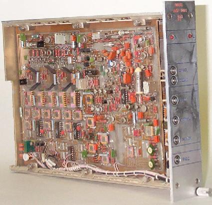
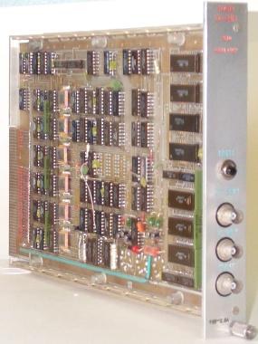
ADC 8100 - 4M size, tracking ADC, TTL memory.
Resolution - 8 bits.
Input ranges - from 0,08V to 10,24V.
Input resistance - 160 KOm.
Conversion rate - from 125 nsec to 50 msec / point.
Memory length - 256 words.
Maximal frequency of processed signal (full amplitude) - 70 KHz.
A few devices were produced. Then we bought ECL
memory with capacity 256 bit/package. It allowed us to modify the device.
The ADC board was based on 8-bit DAC implemented
on KT342 transistors, diodes switches and R-2R ladder and a parallel comparator
section implemented on 554SA1 (15 comparators). The parallel section measured
a difference between input signal and comparator voltage then an error
code was added to DAC code by ALU. |
ADC 8100M - 4M size, tracking ADC,
ECL memory.
Resolution - 8 bits.
Input ranges - from 0,08V to 10,24V.
Input resistance - 160 KOm.
Conversion rate - from 125 nsec to 50 msec / point.
Memory length - 256 words.
Maximal frequency of processed signal (full amplitude) - 70 KHz.
This device consumpted less energy than previous
version. |
 ADC 8100.2 - 4M size, tracking ADC, DRAM memory (memory board
was developed by Batrakov A.).
ADC 8100.2 - 4M size, tracking ADC, DRAM memory (memory board
was developed by Batrakov A.).
Resolution - 8 bits.
Input ranges - from 0,08V to 10,24V.
Input resistance - 160 KOm.
Conversion rate - from 1,25 mcsec to 50 msec / point.
Memory length - 4096 words.
Maximal frequency of processed signal (full amplitude) - 70 KHz.
These modules were produced not many. A reason of
creating this version were difficulties with manufacturing ADC101 boards.
We produced a few ADC8100.2 devices to satisfy urgent needs. This device
was able to work with our multiplexer KAS-4 in multichannel systems. |
ADC 101 - 4M size, successive-approximation
ADC, DRAM memory.
Resolution - 10 bits.
Input ranges - from 0,1V to 8,192V.
Input resistance - 15 KOm.
Conversion rate - from 1 mcsec to 2 msec / point.
Memory length - 4096 words.
Maximal frequency of processed signal (full amplitude) - 200 KHz.
This device had a very complicated biography. Main
components of ADC were crated and tested by Batrakov and me, jointly. Drawing
schematic, routing PCB, assembling prototype board was done by me. Debugging
first ADC board and next modifications were done by Batrakov. A memory
board was designed by Batrakov and CAMAC-interface board (and tests) were
designed by me. And who is the author then? |
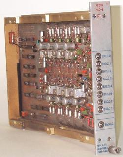
| KAS-4 - 2M size, 4-channel fast analog multiplexer
with input programmable gain amplifiers. It was designed to work with our
digital oscilloscopes ADC101 and ADC8100.2 in multichannel systems. |
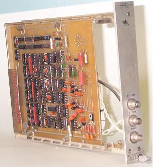
 Manual CAMAC controller. Mr. Batrakov and me were pioneers
in developing CAMAC devices. After assembling our first CAMAC device
we discovered that all our Institute had the only manual controller
and no computer controller at all. We didn't want to wait and made
a pair of that devices.
Manual CAMAC controller. Mr. Batrakov and me were pioneers
in developing CAMAC devices. After assembling our first CAMAC device
we discovered that all our Institute had the only manual controller
and no computer controller at all. We didn't want to wait and made
a pair of that devices. |
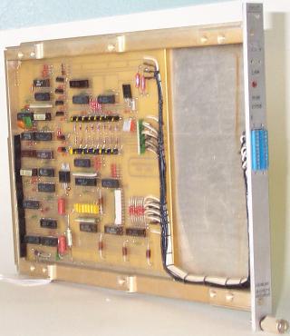
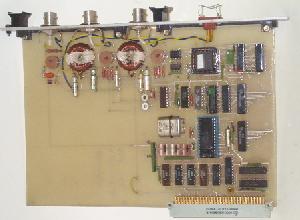
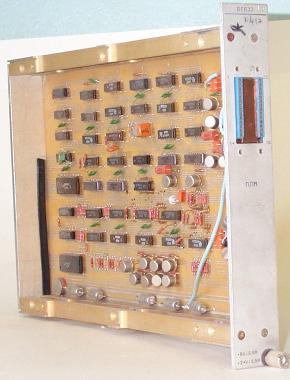
 Dataway display. We had a necessity of CAMAC dataway display.
I had to design it. This device was manufactured in significant volume
(hundreds modules). Here is shown a photo of second version (a first
version included two PCBs).
Dataway display. We had a necessity of CAMAC dataway display.
I had to design it. This device was manufactured in significant volume
(hundreds modules). Here is shown a photo of second version (a first
version included two PCBs). |
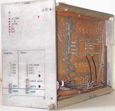
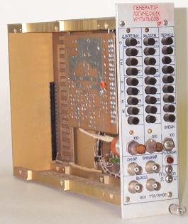 Generator. We had a shortage of different test equipment. We had
no convenient pulse generators. Most of russian industrial generators
loved to die after occasional short-circuit of output. Traditionally,
I assembled prototype during week end, then assistants made a serial
version. The device was implemented in CAMAC standard to avoid making
power supply. The device was not controlled by CAMAC. It only used
power suply of CAMAC crate. This device is used now.
Generator. We had a shortage of different test equipment. We had
no convenient pulse generators. Most of russian industrial generators
loved to die after occasional short-circuit of output. Traditionally,
I assembled prototype during week end, then assistants made a serial
version. The device was implemented in CAMAC standard to avoid making
power supply. The device was not controlled by CAMAC. It only used
power suply of CAMAC crate. This device is used now. |
1980-1981
USSR electronics industry was developing these years.
When we bought 1Kbit MOS memory, we immediately decided to make our digital
oscilloscope set more technological and reliable. Newest ICs allowed to
design a single interface/memory (2K*12bit) board. We used with this board
the same ADC boards (tracking ADC and successive-approximation ADC).
In these years was designed a new fast multiplexor (KAS-8). There was introduced
in our product line a new device type- a pulse voltmeter. And now the same
but in more detail.
ADC8500 (C0638)- 3M size, tracking
ADC.
Resolution - 8 bits.
Input ranges - from 0,08V to 10,24V.
Input resistance - 160 KOm.
Conversion rate - from 500 nsec to 50 msec / point.
Memory length - 256 words.
Maximal frequency of processed signal (full amplitude) - 70 KHz.
It's possible using with KAS-8 in multichannel systems. |
 ADC101M (C0615)- 3M size, successive-approximation ADC.
Resolution - 10 bits.
Input ranges - from 0,1V to 8,192V.
Input resistance - 15 KOm.
Conversion rate - from 1 mcsec to 2 msec / point.
Memory length - 2048 words.
Maximal frequency of processed signal (full amplitude) - 200 KHz.
It's possible using with KAS-8 in multichannel systems. |
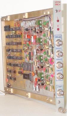
 KAS-8 (A0634)- 2M size, 8-channel fast analog multiplexer with
input programmable gain amplifiers. It was designed to work with our
digital oscilloscopes ADC101M and ADC8500 in multichannel systems.
KAS-8 (A0634)- 2M size, 8-channel fast analog multiplexer with
input programmable gain amplifiers. It was designed to work with our
digital oscilloscopes ADC101M and ADC8500 in multichannel systems.
Input channels - 8.
Settlement time - 500 ns.
Gain 1,0 or 0,25.
Input range - 8 V.
Output swing - 2 V.
Input resistance - 40 Kohm. |
 ZIIS-4 (C0639)- a pulse voltmeter. It consists of four sample-and-hold
and ADC.
ZIIS-4 (C0639)- a pulse voltmeter. It consists of four sample-and-hold
and ADC.
Resolution - 10 bits.
Accuracy - 0,1%.
Input range - 2046 mV.
Input resistance - 1 KOhm.
Settlement time - 2 mcsec.
Maximal frequency of processed signal (full amplitude) - 20 KHz. |
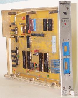
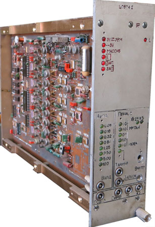
1982
 This
year I developed next version of CAMAC dataway display. It was compact
version, 1M size. But most users preferred old version (2M size). This
year I developed next version of CAMAC dataway display. It was compact
version, 1M size. But most users preferred old version (2M size).
This year I participated in developing a digital oscilloscope
based on storage tube ("Magnolia"). This device was developing by all
of us (Batrakov, Chukanov). I dealed with digital part of device. Reading,
digital processing (detecting screen defects, removing defect areas, determining
curve of signal) and transferring data to CAMAC. Here was used a pair
of interacting microcontrollers. This experience allowed me using arbitrary
microcontrollers in single system without any problems in their interaction.
It's pity but I haven't photo of this device.
Parameters of "Magnolia" digital oscilloscope
Resolution - 7 bits
Iput range - from 0,128 V to 16,384 V
Input resistance - 50 Ohm
Maximal frequency of processed signal (0,7 level) - 130 MHz.
Horizontal resolution - 128 points
paasas - from 64 ns to 8192 ns
Horizontal nonlinearity - 2%
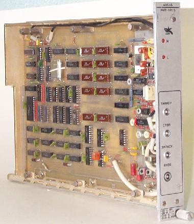
1983-1984
 That time I decided to make a CAMAC controller. We used K0601 controller.
It suited users from installations, but it didn't suit me as CAMAC
designer. To check a presence or absence of X/L signals I should waste
a lot of time and efforts. Checking Q signal reuired about 1 second.
It was easily to check reaction of device on F8 command by manual
controller than by computer test. It was reason for my design. My
crate-controller (K0612) was compatible with K0601 (old program could
work with new controller without modification) but provided a number
of new opportunities. It was possible to read X and Q state by single
command, it was possible read all LAMs by single command. There was
used a pair of microcontrollers.
That time I decided to make a CAMAC controller. We used K0601 controller.
It suited users from installations, but it didn't suit me as CAMAC
designer. To check a presence or absence of X/L signals I should waste
a lot of time and efforts. Checking Q signal reuired about 1 second.
It was easily to check reaction of device on F8 command by manual
controller than by computer test. It was reason for my design. My
crate-controller (K0612) was compatible with K0601 (old program could
work with new controller without modification) but provided a number
of new opportunities. It was possible to read X and Q state by single
command, it was possible read all LAMs by single command. There was
used a pair of microcontrollers.
We produced about 50 controllers K0612. |
 USSR
electronics industry was developing these years. When we bought ADC
chip with 10 bits resolution and 1mcs time conversion we decided to
renew our digital oscilloscope set. Newest ICs allowed to reduce hardware
and improve performance of devices. It was to be expected a lot of
new digital oscilloscopes. To reduce software expenses of mine and
our customers I composed a standard of interface. It was a "S" series,
that means a standartizied device. All new designed digital oscilloscopes
had to have an identical set of commands, registers and ranges. I
had participation in designing a pair models of devices- ADC-101S
and ADC-850S. After this our young designers, directed by Batrakov,
developed about five models of devices. All of them were testing by
single test set. After appearance of next model I added a few constants
in tests (real resolution, size of memory, using ranges from standard
set, presence of analog multiplexer and etc.). USSR
electronics industry was developing these years. When we bought ADC
chip with 10 bits resolution and 1mcs time conversion we decided to
renew our digital oscilloscope set. Newest ICs allowed to reduce hardware
and improve performance of devices. It was to be expected a lot of
new digital oscilloscopes. To reduce software expenses of mine and
our customers I composed a standard of interface. It was a "S" series,
that means a standartizied device. All new designed digital oscilloscopes
had to have an identical set of commands, registers and ranges. I
had participation in designing a pair models of devices- ADC-101S
and ADC-850S. After this our young designers, directed by Batrakov,
developed about five models of devices. All of them were testing by
single test set. After appearance of next model I added a few constants
in tests (real resolution, size of memory, using ranges from standard
set, presence of analog multiplexer and etc.).
ADC-101S
This design was made with Batrakov (he designed
sample-and-hold for device).
Parameters of digital oscilloscopes
C0616 (ADC-101S)
Resolution - 10 bits.
Input ranges - from 0,1V to 8,192V.
Input resistance:
for 1.28-10.24 ranges - 100 KOm
for 0.08-0.64 ranges - 425 KOm
Conversion rate - from 1 mcsec to 2 msec / point (it is possible to
use an external generator)
Memory length - 4096 words.
Maximal frequency of processed signal (full amplitude):
for 1.28-10.24 ranges - 400 KHz
for 0.08-0.64 ranges - 100 KHz
It's possible using with KAS-8 in multichannel systems. |
ADC-850S
Parameters of digital oscilloscopes
C0621 (ADC-850S)
Resolution - 8 bits.
Input ranges - from 0,1V to 8,192V.
Input resistance - 50 Ohm
Maximal frequency of processed signal (full amplitude):
for 1.28-10.24 ranges - 4 MHz
for 0.08-0.64 ranges - 400 KHz
Conversion rate - from 50 nsec to 2 msec / point (it is possible to
use an external generator)
Memory length - 1024 words. |
1985
 That year
I designed a new version of ZIIS using a modern ICs. A new version
was compatible with previous design but it was more simple and cheap. That year
I designed a new version of ZIIS using a modern ICs. A new version
was compatible with previous design but it was more simple and cheap.
Parameters of C0643 (ZIIS-4M)
Resolution - 10 bits.
Accuracy - 0,1%.
Input range - 2046 mV.
Input resistance - 1 KOhm.
Settlement time - 2 mcsec.
Maximal frequency of processed signal (full amplitude) - 20 KHz. |
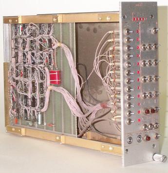
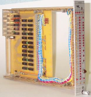
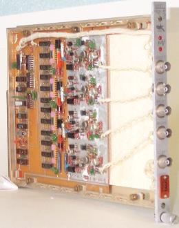
| These years our designers began to use microcomputer
Odrenok instead of minicomputer ODRA-1325. That microcomputer provided
a fast and convenient access to CAMAC dataway. An user programm spent only
25 mcsec for execution of CAMAC command. An access to remote crate via
existing serial link required a few millisecond. To provide a fast access
to remote CAMAC crate I designed a pair of devices (DS-24S and CC-24S)
and wrote a pair software packages for user programs and a set of test
programmes of general purpose (a manual controller emulator, system test
and etc). A new software (and developed hardware) allowed to make application
programs which was able to work with hardware in different crates (in central
crate and in remote crates) without recompilation. We produced hundreds
of these devices. Photos of developed devices are shown below. |
 |
 |
1986-1992
That period I was dealing with programming and small
jobs. I designed a few VME devices together with my colleges. It is pity
but I haven't Photos of these devices. I participated in designing VME
processor module based on 1801WM3 chip, 4*RS-232 interface, arbiter module.
I designed also memory board a few Mbytes. Then perestrojka came and my
colleges went away for best life and this theme was closed.
I designed also a pair of programmers. One of them
was intended to programm PALs 1556 series (PAL16L8, PAL16Rx). The second
device was able to program all russian MOS EPROMs. Photos of these devices
are shown below.
 I
was codesigner of programmer 556RT1,2 (82S100, 101). At first, this
job was doing by my college Kolya Uwarov. The device wanted to have
two PCBs. He asked me to help. I minimized a few schematics, so device
didn't require another board. After that my participation in this
design was completed. I
was codesigner of programmer 556RT1,2 (82S100, 101). At first, this
job was doing by my college Kolya Uwarov. The device wanted to have
two PCBs. He asked me to help. I minimized a few schematics, so device
didn't require another board. After that my participation in this
design was completed. |
 At the
end of this period I designed together with my postgraduated student
Andrey Akulov PC-version of my DS-24S. We produced a few boards of
this device, but users tryed this CAMAC interface didn't want to change
it for widely spreading PPI. The reason was that user received with
board a lot of software (library, manual controller emulator, system
test, CAMAC dataway test, software for PLD and EPROM programmers).
Users of PPI cannot get this software up to now. At the
end of this period I designed together with my postgraduated student
Andrey Akulov PC-version of my DS-24S. We produced a few boards of
this device, but users tryed this CAMAC interface didn't want to change
it for widely spreading PPI. The reason was that user received with
board a lot of software (library, manual controller emulator, system
test, CAMAC dataway test, software for PLD and EPROM programmers).
Users of PPI cannot get this software up to now. |
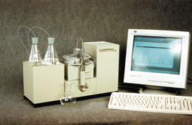
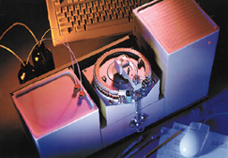
1993-1995
These years I designed electronics for Micro-HPLC System
(EnviroChrom, Milichrom-A02). It was quite heavy job. I dealed with 3 board
with microprocessors (one PCB contained 2 microprocessors). Embedded software
was written in assembler. These programs contains above 5000 lines (32-bits
mathematics, logarithmes and etc). Besides embedded software there were
written a few test programs in PC to debug each part of all device. This
device is prodused now and is selling by a few traders.
Official parameters (from Econics catalogue)
MiliChrom A-02
The device is intended for
using in stationary, mobile or field laboratories performing analizes for
industry and science.
-
A typical sensitivity of anylize:
- in concentration 0,1 - 1 mg/L
- in amount 1 - 10 ng
-
A number of substacies detected
in sigle sample may be up to 25-30.
-
Time of analize procedure is
3-30 minutes depending from sample.
1998-1999
These years I returned to hardware designing. VME interface
for CC-24S was designed together with Vlad Shilo. A pair of VME devices were designed
together with Vladimir Repkov. They are a VME interface for wire beam sensor and
a specialized VME device for wiggler automation. These device aren't general purpose
devices and I will not describe them in detail. Device photos are shown below.
My latest designs have a special page,
look at it.
|