..Introduction..
. ..Project..
. ..Publications..
. ..News..
. ..Links..
. ..For Investors..
. .. ..
..
The source of high voltage is a stage generator with an inductive link and parallel feeding of stages
from the industrial compact powerful electron accelerator of ELV type.
Design of HV-rectifier
Inside the tank filled with an insulating gas (SF6) there are: the primary winding, a column of rectifying sections, magnetic conduits of the return flow (bottom and cylindrical). The primary winding has 32 turns of the water cooled copper pipe. It generates the longitudinal alternate magnetic field with the feeding mains frequency of 400 Hz. The primary winding turns are isolated from the high-voltage gap by an electrostatic shield made of a thin sheet of stainless steel.
In comparison with "conventional" transformers this design is distinguished by the absence of the central magnetic conduit. The primary winding is "wrapped" by the magnetic conduit. Two additional magnetic conduits are located at the bottom of tank and over the high-voltage electrode. These magnetic conduits remove excessive heat caused by eddy currents.
The HV rectifier column consists of 37 rectifying sections connected in series. Each section is a coil of the secondary winding and a double voltage circuit based rectifier. The coil has 3000 turns separated by polymer-mica insulation. Maximum voltage of the coil is 20 kV. Thus, the section output voltage can reach the value of 40 kV. The number of sections connected in series determines the maximum output voltage of HV rectifier. Operating voltage of the coil in the project does not exceed 17 kV, i.e. the section voltage is 34 kV. For rectifying the alternate voltage CDL-0.4-800 columns with a current up to 0.4 A and maximum inverse current of 80 kV are used. An inverse voltage of columns does not exceed 34 kV during the source operation. K-15-10-type capacitors are simultaneously used as filters and for protection of HV rectifier elements (coils, diodes) against excessive loads occurred at breakdowns of the vacuum or gas insulation.
The accelerator primary winding is power supplied with an alternate voltage of 400 Hz from the frequency converter. Electric motor converters are attractive because of their low price, simplicity and reliability. They have an acceptable efficiency (65-80 % depending on power). In principle, the static frequency converters can be used as power sources (with the use of IJBT transistors). However, there is no any evident advantages of static converters except may be for their higher efficiency (they have an efficiency factor of 85-92 %).
Stabilization of accelerating voltage
The output voltage stabilization in the high voltage source of a stage-type with and inductive link and parallel power supply of stages was considered. The developed system enables one to keep the accelerating voltage within accuracy higher than 10-3. A system of active suppression of ripples allows keeping the ripples of rectified voltage at the same level.
In details:

M. E. Veis, S. N. Fadeev, N. K. Kuksanov, P. I. Nemytov, V. V. Prudnikov, R. A. Salimov and S. Yu. Taskaev.
Stabilization of accelerating voltage in HV-tandem accelerator for neutron capture therapy.
Preprint BINP 2002-17. Novosibirsk. 2002.
[.html file]
[.pdf filel]
Construction of 1.25 MV source based on the HV sectioned rectifier
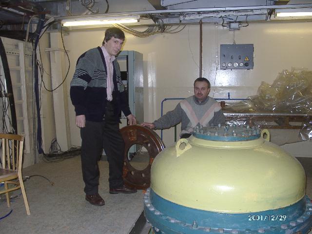
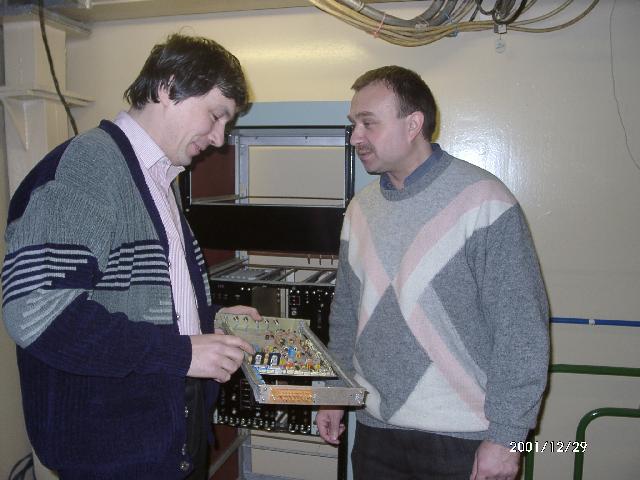
Electric machine transformer PCh-60 used as a transformer for tandem accelerator power supply was placed in a specially prepared building. All elements and systems of high-voltage power supply were completely assembled, namely: primary winding with magnetic circuit, high-voltage rectifier column, controlling system including stabilization system elements, frequency transformer, capacitor bank, power switchboard, gas system, water cooling distributor.


April 2001.


December 2001. High-voltage source was completed with high-voltage electrode from ELV accelerators which slightly differ from high-voltage electrode of tandem accelerator. This procedure allowed conducting of high voltage tests of the source. A set of tests were fulfilled "in air" at low voltage of 140 kV. Then, the high-voltage source was covered with large tank and filled with isolating gas SF6 at pressure of 5 absolute atmospheres. During tests in the isolating gas atmosphere the voltage was up to of 1.4 MV. At these parameters, the source was successfully tested in prolonged nonstop run, which showed stable work without breakdowns for 3 days and nights.


© 1999-2012 Sergey Taskaev. Please contact on any questions the project and the site and proposals.